Audio Processing
Signal processing pipeline
The XVF3610 audio processing pipeline takes inputs from a pair of MEMS Pulse Density Modulation (PDM) microphones and uses advanced signal processing to create audio streams suitable for use in Automatic Speech Recognition (ASR) and voice communication applications. The block diagram of this audio processing pipeline is shown in the figure below.
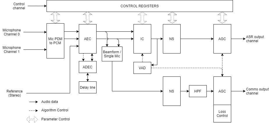
Fig. 9 The XVF3610 audio processing pipeline
The pipeline enhances the captured audio stream using a set of complementary signal enhancement and noise reduction processes:
Microphone PDM to Pulse Code Modulation (PCM) conversion: Converts the PDM audio input from the microphones into PCM format allowing further processing.
Acoustic Echo Cancellation (AEC): enables the XVF3610 to detect voice signals in the presence of high volume, stereo audio from the product into which it is integrated. This process takes the stereo audio from the product as a reference signal and models the echo characteristics between each speaker and microphone caused by the acoustic environment of the device and room. These four models are used to continuously remove the echoes from out the audio outputs from the microphone audio input. The models are continuously adapted to the acoustic environment to accommodate changes in the room created by events such as doors opening or closing and people moving in the room.
The Automatic Delay Estimation Control (ADEC): automatically monitors and manages the delay between the reference audio and the echo received by the microphone to ensure optimal AEC cancellation when the audio output latency is variable or non-zero.
Interference Cancellation (IC): suppresses static noise from point sources such as cooker hoods, washing machines, or radios for which there is no reference audio signal available. When an internal Voice Activity Detector (VAD) indicates the absence of voice, the IC adapts to suppress point noise sources in the environment. When voice is detected adaption is suspended maintaining suppression of the interfering noise source.
Noise Suppression (NS): suppresses diffuse noise from sources whose frequency characteristics do not change rapidly over time such as air conditioning or city background noise.
Automatic Gain Control (AGC): tunes separate AGC channels for Automatic Speech Recognition and communications output. The internal VAD is used to prevent gain changes in the ASR output channel during speech to improve speech recognition performance.
Reference signal delay
As shown above, the XVF3610 includes an Automatic Delay Estimator Control(ADEC) which is used to time-align the reference and microphone signals, allowing the Acoustic Echo Canceller (AEC) to work effectively. This is an essential aspect of device operation for situations where the audio output path is unknown, such as in TVs and set-top box architectures.
The ADEC applies a time shift to one of the signals based on an automatic estimate between them, or a user-defined delay, to deliver a synchronised input to the AEC.
A delay of between 0-150ms can be applied to either the reference signal or microphone input, equivalent to 0-2400 samples at 16kHz sample frequency.
The ADEC runs in one of three modes:
Automatic - the ADEC runs immediately after the device starts. It constantly monitors the reference signal and microphone input for changes of time alignment and automatically adjusts its delay as necessary.
Manual – in this mode, the ADEC waits in a disabled state until the device is manually triggered by the host. The delay is estimated at the trigger point, or a selected fixed delay applied. The delay set will be used until it is changed by:
manually applying a different fixed delay.
manually triggering a new delay estimate.
switching to automatic mode.
Estimate on Start-up (default) - The ADEC runs immediately after the device starts, calculates the delay between the two signals and applies that delay to all subsequent signals. After making the initial delay estimate and delay setting, no further changes will be made unless manually triggered or automatic mode is selected.
For further information on the usage of ADEC please refer to the XVF3610 User Guide.
Example applications
The essential components and signals for a XVF3610-INT application using QSPI flash memory with 1V8 I/0 is shown in the figure below.
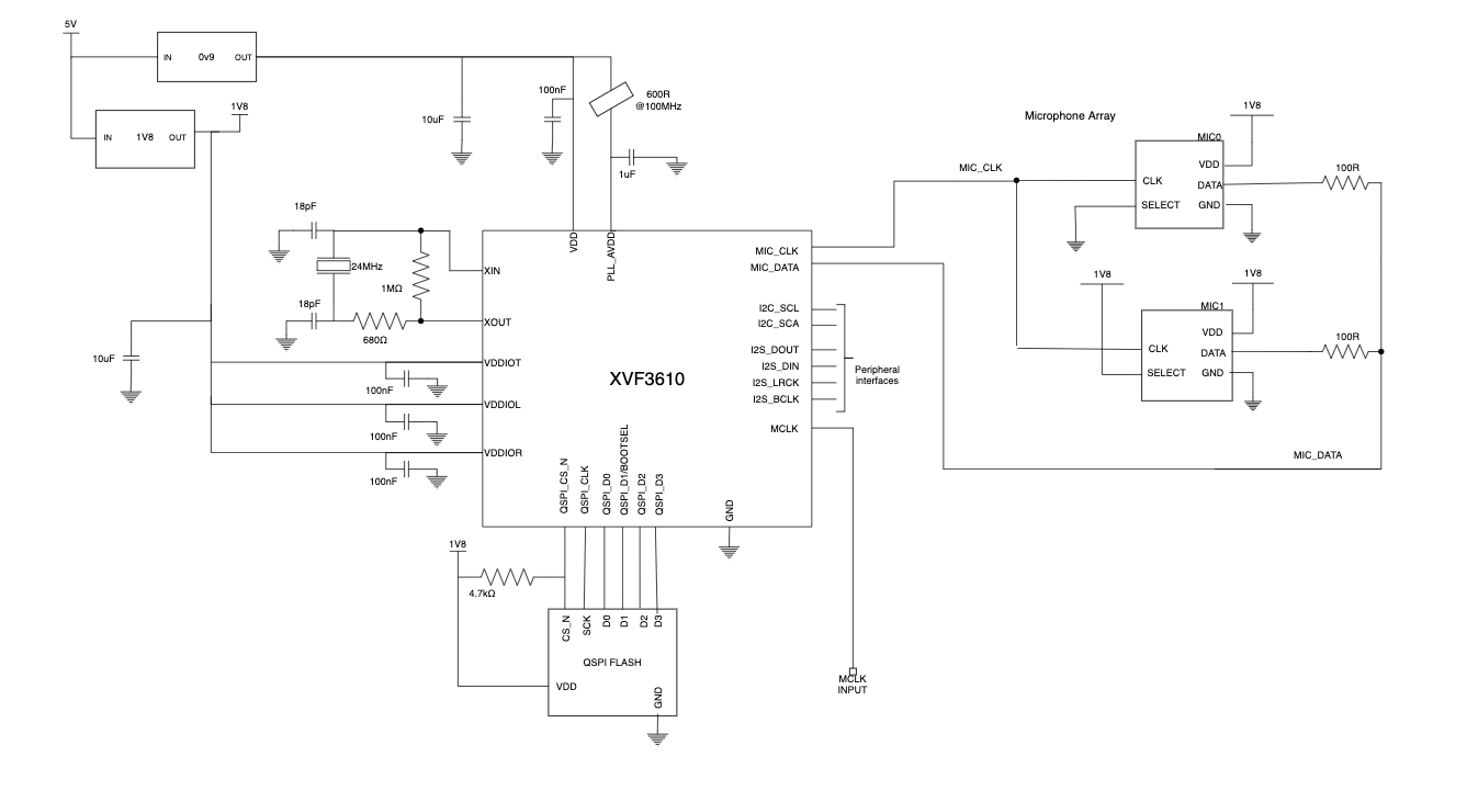
Fig. 10 Essential components of an XVF3610-INT application with VDDIO = 1V8
The essential components and signals for a XVF3610-UA application with 3V3 I/0 is shown in the figure below.
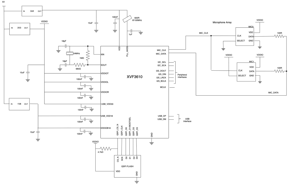
Fig. 11 Essential components of an XVF3610-UA application with 3V3 IO