SPI Master
The XVF3610-UA and XVF3610-INT variants provide an SPI master interface which can be used as:
a bridge from the USB interface, i.e.
vfctrl_usbcommands can be used from the host to read and write devices connected to the SPI Peripheral Port; anda mechanism to initialise devices connected to the SPI Peripheral Port by incorporating commands into the Data Partition (in the external flash), which are executed at boot time.
NOTE: From Version 4.1 the SPI Master peripheral interface is not available on XVF3610-UA and XVF3610-INT devices that have been SPI booted to prevent possible bus contention issues
The SPI master peripheral supports the following fixed specifications:
Single chip select line
1Mbps fixed clock speed
Supports either reads or writes. Duplex read/writes are not supported.
Most significant bit transferred first
Mode 0 transfer (CPOL = 0, CPHA = 0)
NOTE: The chip select is asserted a minimum of 20ns before the start of the transfer and de-asserted a minimum of 20ns after the transfer ends.
The SPI Master is controlled using the following commands.
COMMAND |
TYPE |
ARGS |
DESCRIPTION |
|---|---|---|---|
GET_SPI |
uint8 |
56 |
Gets the contents of the SPI read buffer. |
GET_SPI_READ_HEADER |
uint8 |
2 |
Get the address and count of next SPI read. |
SET_SPI_PUSH |
uint8 |
56 |
Push SPI command data onto the execution queue. |
SET_SPI_PUSH_AND_EXEC |
uint8 |
56 |
Push SPI command data and execute the command from the stack. Data will then be sent to SPI device. |
SET_SPI_READ_HEADER |
uint8 |
2 |
Set address and count of next SPI read. |
Reads of up to 56 Bytes at a time may be performed but writes of 128 Bytes at a time can be made by pushing multiple commands into a command stack and executing them in one go. The transaction is performed within a single chip select assertion.
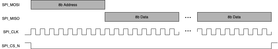
Fig. 35 SPI peripheral, read sequence
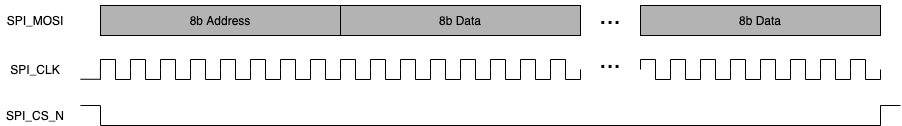
Fig. 36 SPI peripheral, write sequence
The control protocol does not support variadic (variable number of) arguments. Hence, even when writing a single byte, the total number of arguments passed must be the maximum. Unwritten values are ignored.
See below examples.
The following example writes one byte of data (with value 122) to a control register as address 6.
vfctrl_i2c SET_SPI_PUSH_AND_EXEC 0 0 0 0 0 0 0 0 0 0 0 0 0 0 0 0 0 0 0 0 0 0 0 0 0 0 0 0 0 0 0 0 0 0 0 0 0 0 0 0 0 0 0 0 0 0 0 0 0 0 0 0 0 6 1 122
NOTE: All numbers are decimal. It is necessary to pad the payload to 56
bytes, which includes the address, length and data values. This is a
requirement of the vfctrl tool, the SPI interface itself will only
transmit the valid data.
Transmitting more than 54 bytes of data is possible using the SET_SPI_PUSH command to queue up data, using multiple commands before the push is executed. The following example writes values 0 to 69 to address 100 (70 bytes in total) using command to push 56 data values into the queue, followed by a push the remaining 14 data words and then execute the transfer:
vfctrl_i2c SET_SPI_PUSH 55 54 53 52 51 50 49 48 47 46 45 44 43 42 41 40 39 38 37 36 35 34 33 32 31 30 29 28 27 26 25 24 23 22 21 20 19 18 17 16 15 14 13 12 11 10 9 8 7 6 5 4 3 2 1 0
vfctrl_i2c SET_SPI_PUSH_AND_EXEC 0 0 0 0 0 0 0 0 0 0 0 0 0 0 0 0 0 0 0 0 0 0 0 0 0 0 0 0 0 0 0 0 0 0 0 0 0 0 0 0 100 70 69 68 67 66 65 64 63 62 61 60 59 58 57 56
To read one byte at address 6, which contains the value 122, do the following:
vfctrl SET_SPI_READ_HEADER 6 1
vfctrl GET_SPI
> GET_SPI: 122 0 0 0 0 0 0 0 0 0 0 0 0 0 0 0 0 0 0 0 0 0 0 0 0
-> 0 0 0 0 0 0 0 0 0 0 0 0 0 0 0 0 0 0 0 0 0 0 0 0 0 0 0 0 0 0 0
To read 16 bytes from address 0, which all contain the value 33, do the following:
vfctrl SET_SPI_READ_HEADER 0 16
vfctrl GET_SPI
> GET_SPI: 33 33 33 33 33 33 33 33 33 33 33 33 33 33 33 0 0 0 0
-> 0 0 0 0 0 0 0 0 0 0 0 0 0 0 0 0 0 0 0 0 0 0 0 0 0 0 0 0 0 0 0 0 0 0 0