Wake Word Integration
The key feature that the XVF3615 adds to the standard XVF3610 is the inclusion of an Amazon 250kB wake-word engine (WWE). The WWE is connected to the output from the audio processing pipeline, and it monitors the audio stream for the “Alexa” keyword.
In normal operation the AVS client on the host will be reading the audio data from the XVF3615 and storing the data locally in the standard Shared Data Service ring buffer included in the AVS client SDK. The figure below shows the integration points between the XVF3615 and a standard AVS Client.
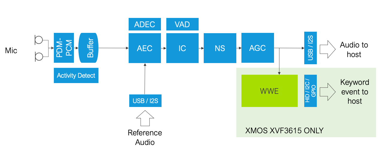
Fig. 40 Connection between XVF3615 and AVS client
When a keyword is detected the AVS client on the host will be notified of the wake word detection through either a USB HID report or an interrupt from a output pin on the device.
This guarantees that the host is notified of the keyword in a specific latency window without requiring polling of the XVF3615.
Once the host has been notified of the keyword detection it should immediately read the wake word
start and end index values via the vfctrl interface.
Note
The wake word start and end indexes are reported by the XVF3615 with respect to the audio samples that it is streaming. The AVS client has to take into account any processing delay in the host.
vfctrl_usb GET_WWE_INDEXES
This command returns three 64bit values as shown in the table below.
Index |
Value |
Note |
|---|---|---|
0 |
Current_index |
Free running. Host can read current value at any time |
1 |
WW_start_index |
WWE index at start of wake word |
2 |
WW_end_index |
WWE index for the end of the wake word |
Note
The WW_start_index and WW_end_index values are only updated following a wake word detection. The host can execute the GET_WWE_INDEXES at anytime to read the current value of the XVF3615 counter.
These two WW index values can be used by the AVS client to compute the appropriate offset into the SDS ring buffer to allow the AVS client to start sending data from that buffer, including the required 0.5 second pre-roll data, to the AVS cloud service for second stage validation and command processing.
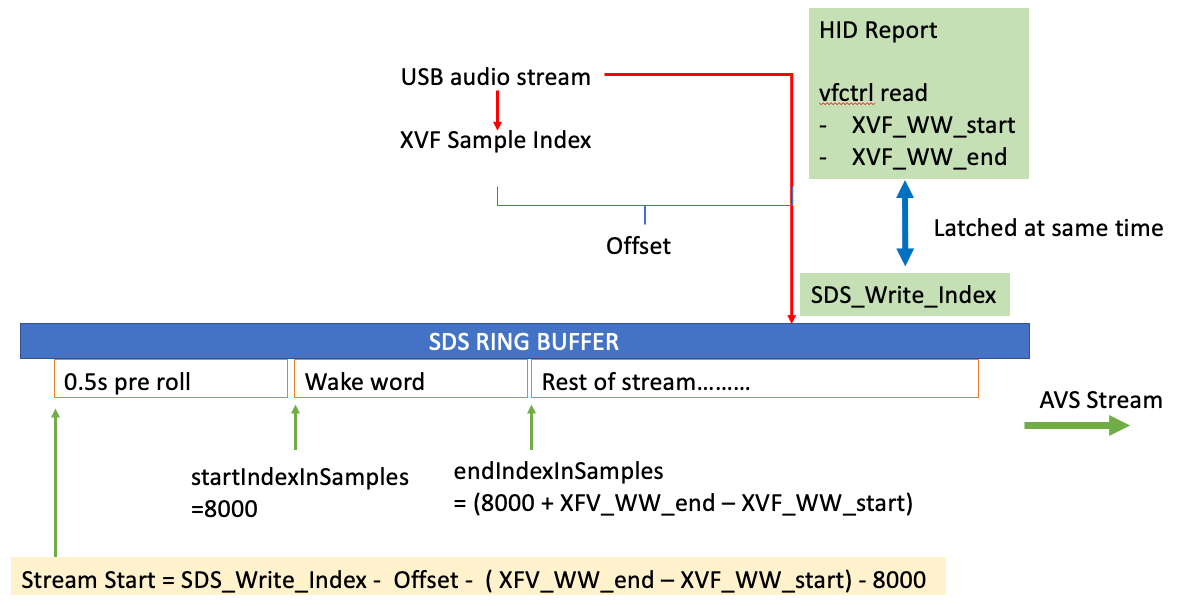
Fig. 41 Calculation of start of buffer to stream to AVS
Depending on the design of the client on the host there may be an offset between the time that the host recieves a wake word is notified and the time the client processes the notification, as shown in the the figure above.
In order to compute this offset, the XVF3615 supports a mechanism that
enables the SoC to measure the latency. If the SoC issues a GET_WWE_INDEXES
vfctrl command the XVF3615 will respond with the current value of the sample counter.
The offset can then be calculated as the difference between the returned XVF counter and
the SDS buffer write pointer value at time the client reads the sample counter.
The AVS client can also synchronise periodically to correct for any drift due to latency or other timing variations in the host.
Both the synchronisation process and the wake word detection process are shown in the following diagram.
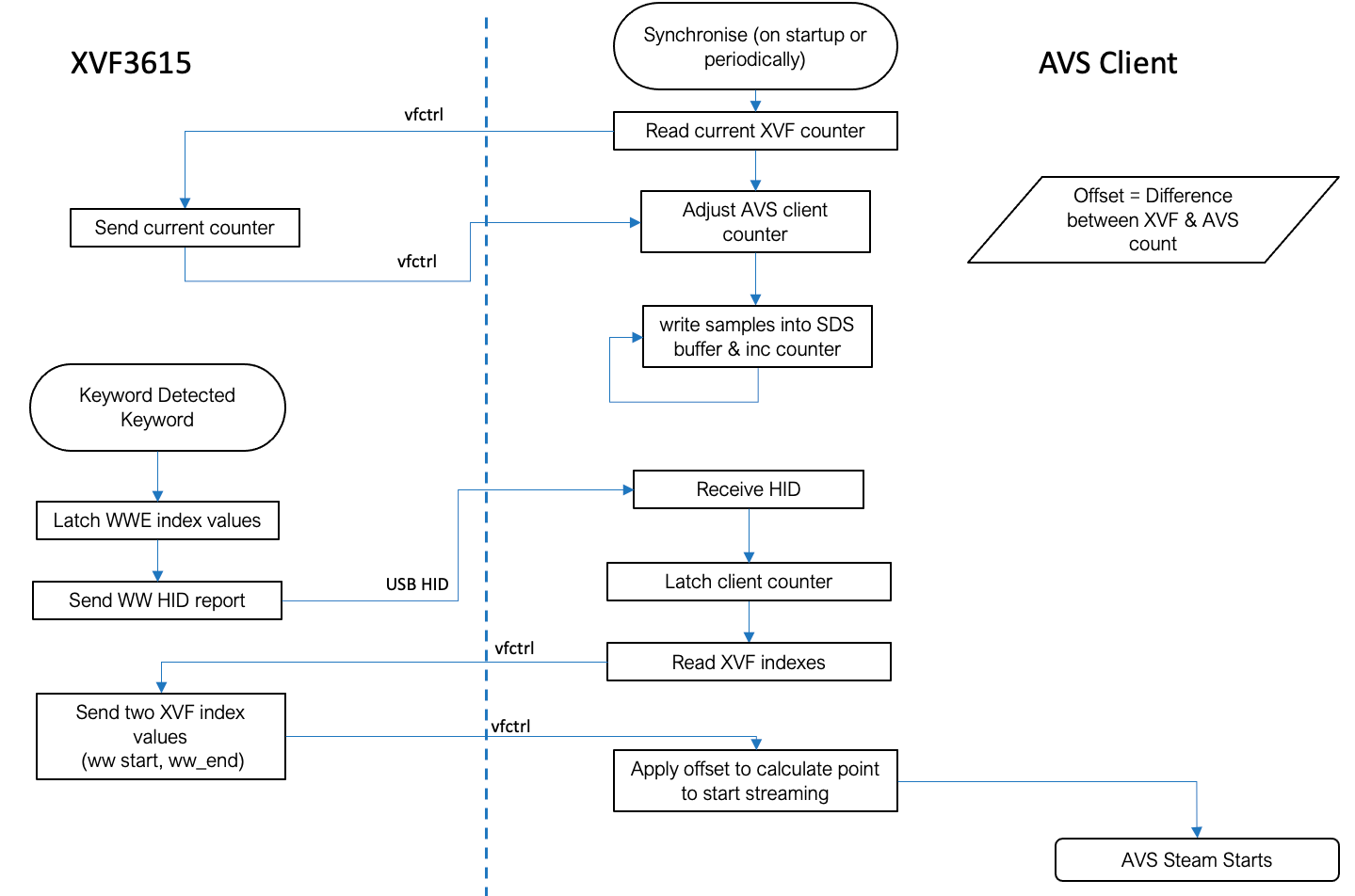
Fig. 42 Interaction between AVS client and XVF3615
Note
If the XVF3615 is used in the -INT configuration, the send HID report function
in the diagram will be replaced with the XVF sending an interrupt pulse via the
GPO to the host, but the mechanism to read the WW index from the device is the
same, using the vfctrl_i2c interface.