General Purpose Input and Output and Peripheral Bridging
The XVF3610 supports I/O expansion and protocol bridging over USB and I2C for the XVF3610-UA and XVF3610-INT respectively. This allows peripheral devices such as audio hardware connected to XVF3610 to be configured and monitored by the host.
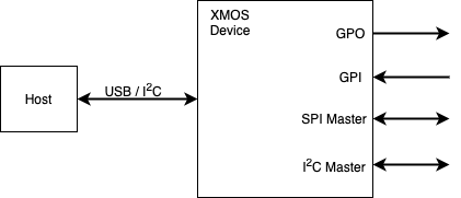
Fig. 30 Device GPIO interfaces
Four GPI channels (pins)
Direct read of port value
Rising, falling or both edge capture with “sticky” bit which is cleared on read
Mode configurable per pin
Four GPO channels (pins)
Direct write of entire port or pin
Active high or Active low
500Hz PWM configurable between 0 and 100% duty cycle
Blinking control supporting a sequence of 32, 100ms states
SPI Master
1Mbps SPI clock
Up to 128 Bytes SPI write
Up to 56 Bytes SPI read
I2C Master (XVF3610-UA only)
100kbps SCL clock speed
Register read/write (byte)
Up to 56 byte I2C read/write
The following sections describe the configuration and usage of each peripheral interface.