Overview#
lib_mic_array is a library for capturing and processing PDM microphone data
on xcore.ai devices.
PDM microphones are a kind of ‘digital microphone’ which captures audio data as a stream of 1-bit samples at a very high sample rate. The high sample rate PDM stream is captured by the device, filtered and decimated to a 32-bit PCM audio stream.
Capabilities#
Both SDR (1 mic per pin) and DDR (2 mics per pin) microphone configurations are supported
Configurable clock divider allows user-selectable PDM sample clock frequency (3.072 MHz typical)
Configurable two-stage decimating FIR filter
First stage has fixed tap count of 256 and decimation factor of 32
Second stage has fully configurable tap count and decimation factor
Custom filter coefficients can be used for either stage
Reference filter with total decimation factor of 192 is provided (16 kHz output sample rate w/ 3.072 MHz PDM clock)
Supports 1-, 4- and 8-bit ports.
Supports 1 to 16 microphones
Includes ability to capture samples on a subset of a port’s pins (e.g. 3 PDM microphones may be used with a 4- or 8-bit port)
Also supports microphone channel index remapping
Optional DC offset elimination filter
Sample framing with user selectable frame size (down to single samples)
Most configurations require only a single hardware thread
High-Level Process View#
This section gives a brief overview of the steps to process a PDM audio stream into a PCM audio stream. This section is concerned with the steady state behavior and does not describe any necessary initialization steps.
Execution Contexts#
The mic array unit uses two different execution contexts. The first is the PDM rx service (“PDM rx”), which is responsible for reading PDM samples from the physical port, and has relatively little work to do, but also has a strict real-time constraint on reading port data in a timely manner. The second is the decimation thread, which is where all processing other than PDM capture is performed.
This two-context model relaxes the need for tight coupling and synchronization between PDM rx and the decimation thread, allowing significant flexibility in how samples are processed in the decimation thread.
PDM rx is typically run within an interrupt on the same hardware core as the decimation thread, but it can also be run as a separate thread in cases where many channels result in a high processing load.
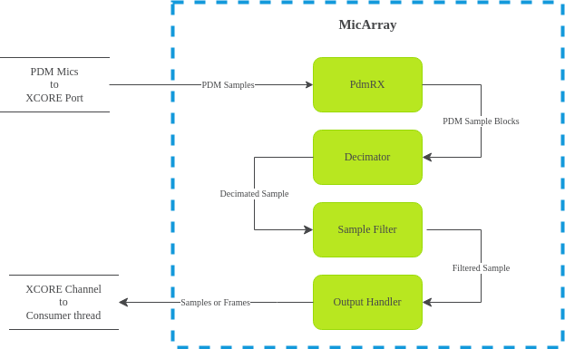
Step 1: PDM Capture#
The PDM data signal is captured by the xcore.ai device’s port hardware. The port receiving the PDM signals buffers the received samples. Each time the port buffer is filled, PDM rx reads the received samples.
Samples are collected word-by-word and assembled into blocks. Each time a block has been filled, the block is transferred to the decimation thread where all remaining mic array processing takes place.
The size of PDM data blocks varies depending upon the configured number of microphone channels and the configured second stage decimator’s decimation factor. Each PDM data block will contain exactly enough PDM samples to produce one new mic array (multi-channel) output sample.
Step 2: First Stage Decimation#
The conversion from the high-sample-rate PDM stream to lower-sample-rate PCM stream involves two stages of decimating filters. After the decimation thread receives a block of PDM samples, the samples are filtered by the first stage decimator.
The first stage decimator has a fixed decimation factor of 32 and a fixed
tap count of 256. An application is free to supply its own filter
coefficients for the first stage decimator (using the fixed decimation factor
and tap count), however this library also provides a reference filter for the
first stage decimator that is recommended for most applications.
The first stage decimating filter is an FIR filter with 16-bit coefficients, and
where each input sample corresponds to a +1 or a -1 (typical for PDM
signals). The output of the first stage decimator is a block of 32-bit PCM
samples with a sample time 32 times longer than the PDM sample time.
See Decimator Stages for further details.
Step 3: Second Stage Decimation#
The second stage decimator is a decimating FIR filter with a configurable
decimation factor and tap count. Like the first stage decimator, this library
provides a reference filter suitable for the second stage decimator. The
supplied filter has a tap count of 65 and a decimation factor of 6.
The output of the first stage decimator is a block of N*K PCM values,
where N is the number of microphones and K is the second stage
decimation factor. This is just enough samples to produce one output sample from
the second stage decimator.
The resulting sample is vector-valued (one element per channel) and has a sample
time corresponding to 32*K PDM clock periods. Using the reference filters
and a 3.072 MHz PDM clock, the output sample rate is 16 kHz.
See Decimator Stages for further details.
Step 4: Post-Processing#
After second stage decimation, the resulting sample goes to post-processing where two (optional) post-processing steps are available.
The first is a simple IIR filter, called DC Offset Elimination, which seeks to ensure each output channel tends to approach zero mean. DC Offset Elimination can be disabled if not desired. See Sample Filters for further details.
The second post-processing step is framing, where instead of signaling each
sample of audio to subsequent processing stages one at a time, samples can be
aggregated and transferred to subsequent processing stages as non-overlapping
blocks. The size of each frame is configurable (down to 1 sample per frame,
where framing is functionally disabled).
Finally, the sample or frame is transmitted over a channel from the mic array module to the next stage of the processing pipeline.
Extending/Modifying Mic Array Behavior#
At the core of lib_mic_array are several C++ class templates which are
loosely coupled and intended to be easily overridden for modified behavior. The
mic array unit itself is an object made by the composition of several smaller
components which perform well-defined roles.
For example, modifying the mic array unit to use some mechanism other than a channel to move the audio frames out of the mic array is a matter of defining a small new class encapsulating just the modified transfer behavior, and then instantiating the mic array class template with the new class as the appropriate template parameter.
With that in mind, while most applications will have no need to modify the mic array behavior, it is nevertheless designed to be easy to do so.