Decimator Stages#
The mic array unit provided by this library uses a two-stage decimation process to convert a high sample rate stream of (1-bit) PDM samples into a lower sample rate stream of (32-bit) PCM samples.
Below is a simplified model of the mic array unit.
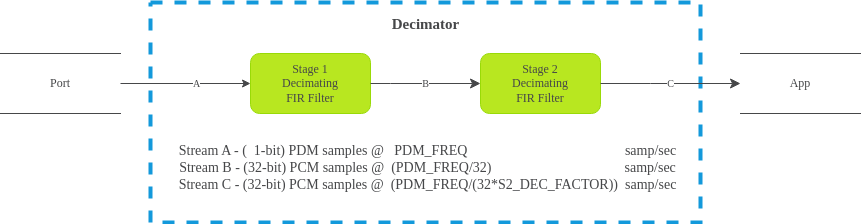
The first stage filter is a decimating FIR filter with a fixed tap count
(S1_TAP_COUNT) of 256 and a fixed decimation factor (S1_DEC_FACTOR)
of 32.
The second stage decimator is a fully configurable FIR filter with tap count
S2_TAP_COUNT and a decimation factor of S2_DEC_FACTOR (this can be
1).
Decimator Stage 1#
For the first stage decimating FIR filter, the actual filter coefficients used
are configurable, so an application is free to use a custom first stage filter,
as long as the tap count is 256. This library also provides coefficients for
the first stage filter, whose filter characteristics are adequate for most
applications.
Filter Implementation (Stage 1)#
The input to the first stage decimator (here called “Stream A”) is a stream of
1-bit PDM samples with a sample rate of PDM_FREQ. Rather than each PDM
sample representing a value of 0 or 1, each PDM sample represents a
value of either +1 or -1. Specifically, on-chip and in-memory, a bit
value of 0 represents +1 and a bit value of 1 represents -1.
The output from the first stage decimator, Stream B, is a stream of 32-bit PCM
samples with a sample rate of PDM_FREQ/S1_DEC_FACTOR = PDM_FREQ/32. For
example, if PDM_FREQ is 3.072 MHz, then Stream B’s sample rate is 96.0 kHz.
The first stage filter is structured to make optimal use of the XCore XS3 vector processing unit (VPU), which can compute the dot product of a pair of 256-element 1-bit vectors in a single cycle. The first stage uses 256 16-bit coefficients for its filter taps.
The signature of the filter function is
int32_t fir_1x16_bit(uint32_t signal[8], uint32_t coeff_1[]);
Each time 32 PDM samples (1 word) become available for an audio channel, those
samples are shifted into the 8-word (256-bit) filter state, and a call to
fir_1x16_bit results in 1 Stream B sample element for that channel.
The actual implementation for the first stage filter can be found in
src/fir_1x16_bit.S. Additional usage details can be found in
api/etc/fir_1x16_bit.h.
Note that the 256 16-bit filter coefficients are not stored in memory as a
standard coefficient array (i.e. int16_t filter[256] = {b[0], b[1], ... };).
Rather, in order to take advantage of the VPU, the coefficients must be
rearranged bit-by-bit into a block form suitable for VPU processing. See the
section below on filter conversion if supplying a custom filter for stage 1.
Provided Filter (Stage 1)#
This library provides filter coefficients that may be used with the first stage
decimator. These coefficients are available in your application through the
header mic_array/etc/filters_default.h as stage1_coef.
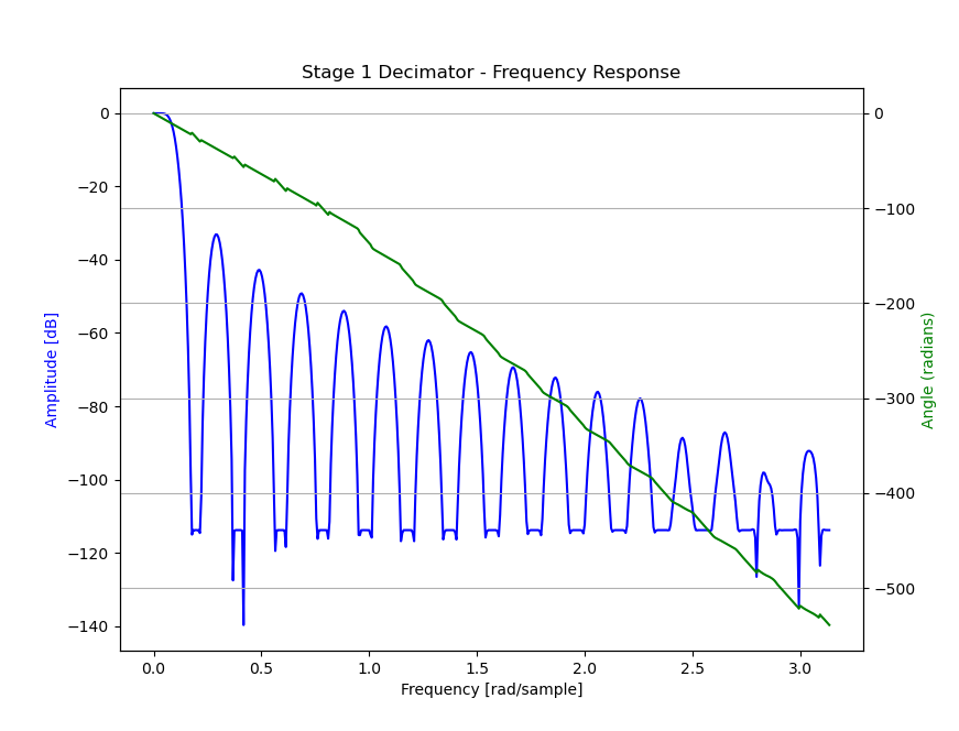
Filter Characteristics (Stage 1)#
The plot below indicates the frequency response of the provided first stage decimation filter.
Filter Conversion Script#
Taking a set of floating-point coefficients, quantizing them into 16-bit coefficients and ‘boggling’ them into the correct memory layout can be a tricky business. To simplify this process, this library provides a Python (3) script which does this process for you.
The script can be found in this repository at script/stage1.py.
Decimator Stage 2#
An application is free to supply its own second stage filter. This library also provides a second stage filter whose characteristics are adequate for many or most applications.
Filter Implementation (Stage 2)#
The input to the second stage decimator (here called “Stream B”) is the stream
of 32-bit PCM samples emitted from the first stage decimator with a sample rate
of PDM_FREQ/32.
The output from the second stage decimator, Stream C, is a stream of 32-bit PCM
samples with a sample rate of PDM_FREQ/(32*S2_DEC_FACTOR). For example, if
PDM_FREQ is 3.072 MHz, and S2_DEC_FACTOR is 6, then Stream C’s
sample rate (the sample rate received by the main application code) is
3.072 MHz / (32*6) = 16 kHz
The second stage filter uses the 32-bit FIR filter implementation from
lib_xcore_math. See
xs3_filter_fir_s32() in that library for more implementation details.
Provided Filter (Stage 2)#
This library provides a filter suitable for the second stage decimator. It is
available in your application through the header
mic_array/etc/filters_default.h.
For the provided filter S2_TAP_COUNT = 65, and S2_DEC_FACTOR = 6.
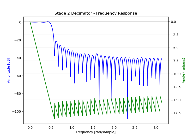
Filter Characteristics (Stage 2)#
The plot below indicates the frequency response of the provided second stage decimation filter.