XFLASH#
Synopsis#
xflash xe-file
xflash [options]
Description#
XFLASH creates binary files in the xCORE flash format, as illustrated in the diagram below. It can also program these files onto flash devices used to boot XMOS systems.
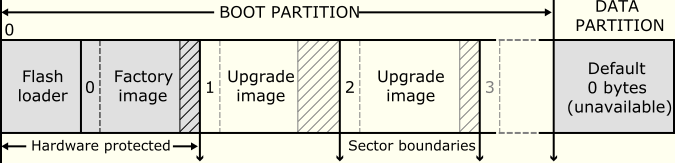
Flash format diagram#
Options#
Overall Options#
The following options are used to specify the program images and data that makes up the binary and its layout. Padding is inserted when required to ensure that images are aligned on sector boundaries.
- --factory <xe-file> [size]#
Specifies <xe-file> as the factory image. If size is specified, padding is inserted to make the space between the start of this image and the next image at least the specified size. The default unit of size is “bytes;” the size can be postfixed with
kto specify a unit of kilobytes.At most one factory image may be specified.
- --upgrade <id> <xe-file> [size]#
Specifies <xe-file> as an upgrade image with version
id. Each version number must be a unique number greater than 0. Ifsizeis specified, padding is inserted to make the space between the start of this image and the next image at least the specified size. The default unit of size is “bytes;” the size can be postfixed withkto specify a unit of kilobytes.Multiple upgrade images are inserted into the boot partition in the order specified on the command line.
If no factory image is specified, a single upgrade image may be specified and written to a file with the option
-o.
- --factory-version <version>#
Specifies version as the tools release master version that was used to create the factory image. Accepted values are: 10, 11, 12, 13.0, 13.1, 13.2, 14.0, 14.1, 14.2, 14.3, 14.4, 15.0, 15.1 and 15.2. This option need only be specified when
--upgradeis provided but--factoryis not. This option will ensure that the produced flash upgrade image is of the correct format for the installed factory image.
- --boot-partition-size <n>#
Specifies the size of the boot partition to be
nbytes. If left unspecified, the default size used is the total size of the flash device.nmust be greater than or equal to the minimum size required to store the boot loader, factory image and any upgrade images. XFLASH will round up the actual boot partition size to the next sector boundary in flash memory.
- --data [flash-name] <file>#
Specifies the contents of
fileto be written to the data partition.For a system with multiple flash boot sites, the data partition of the individual flash devices can be specified separately by repeatedly providing this option with
flash-nameset to the Name attribute of the flash device as defined in the XN file.
- --loader <file>#
Specifies custom flash loader functions in
file, wherefilemay be either an object (.o) or archive (.a).By default, the XTC flash loader selects the image with the highest version number. A custom loader may choose to override the selected image. Only valid images passing CRC checks - and additional signature checks, under secure boot - are considered for selection. The custom loader is not expected to perform this validation and only informs the XTC flash loader which of the available valid images is preferred.
- --idnum <32-bit-integer>#
Specifies a numerical identifier which will be stored in the flash.
- --idstr <a_string>#
Specifies a string identifier which will be stored in the flash.
- --analyze <file>#
Prints the data structures and extracts the individual sections of the xCORE flash binary or flash dump in
file.If the factory image was built using an older tools release, the option
--factory-versionmust be set accordingly. If the flash binary is encrypted,--keycan be specified to enable decryption and signature verification of the sections.The output code sections can be individually disassembled to aid debugging.
- --force#
Disables interactive prompts for user confirmation of any action. This can be used to bypass target warnings without user interaction.
- --verbose#
Prints additional information about the program when loaded onto the target system.
- --help#
Prints a description of the supported command line options.
- --version#
Displays the version number and copyrights.
Target Options#
The following options are used to specify which flash device the binary is to be programmed on. The type of flash device used determines the values for the SPI divider, sector size and memory capacity.
- --list-devices, -l#
Prints an enumerated list of all JTAG adapters connected to the PC and the devices on each JTAG chain, in the form:
ID Name Adapter ID Devices-- ---- ---------- -------The adapters are ordered by their serial numbers.
- --id <ID>#
Specifies the adapter connected to the target hardware.
XFLASH connects to the target platform and determines the type of flash device connected to it.
- --adapter-id <ADAPTER-SERIAL-NUMBER>#
Specifies the serial number of the adapter connected to the target hardware. XFLASH connects to the target hardware and determines the type of flash device connected to it.
- --target-file <xn-file>#
Specifies
xn-fileas the target platform.
- --target <platform>#
Specifies a target platform. The platform configuration must be specified in the file
platform.xn, which is searched for in the paths specified by theXCC_DEVICE_PATHenvironment variable.
- --noinq#
Does not run the device inquirer program. The inquirer queries the device for flash memory density and sector size information. By default the inquirer runs when the user has not supplied the memory density in the XN file.
If
--noinqis omitted XFLASH expects to be able to connect to the xCORE target via JTAG, in order to query the flash device.
- --force-jtag#
Will instruct the program to only communicate over JTAG, and not use the faster xSCOPE link. By default the xSCOPE link is used if declared in the XN file.
This option is recommended only when the xSCOPE link is physically disconnected.
- --force-pll-reset#
Will force an xCORE-200 (XS2) or xcore.ai (XS3) device to reset when the PLL register is written during the boot process. By default the device will not reset when the PLL register is written allowing for faster boot times.
This option is not recommended.
- --jtag-speed <n>#
Sets the divider for the JTAG clock to
n. The corresponding JTAG clock speed is 6/(n+1)MHz. The default value of the divider for the JTAG clock is 0, representing 6MHz.
- --spi-spec <file>#
Enables support for the flash device specified in
file(see Add support for a new flash device).
- --spi-div <n>#
Sets the divider for the SPI clock to
n, producing an SPI clock speed of 100/2*nMHz. By default, if no target is specified, the divider value is set to 3 (16.7MHz).
- --quad-spi-clock <arg>#
Set the Quad SPI clock for the second stage loader.
argmay be one of: 5MHz, 6.25MHz, 8.33MHz, 12.5MHz, 13.88MHz, 15.62MHz, 17.85MHz, 20.83MHz, 25MHz, 31.25MHz, 41.67MHz, 50MHz. By default, the clock is set to 15.62MHz.
- --image-search-page#
Will instruct the second stage bootloader to search flash memory for potential upgrade images at every page boundry within the boot partition. This was the default search mechanism in tools 14.0 and all previous tools versions.
- --image-search-sector#
Will instruct the second stage bootloader to search flash memory for potential upgrade images at every sector boundry within the boot partition. This is the new default search mechanism in tools 14.2.
- --image-search-address <address>#
Will instruct the second stage bootloader to search flash memory for potential upgrade images at a specified address within the boot partition. This option can be provided up to a maximum of three times, allowing for 3 seperate upgrade images to be present within flash memory.
Security Options#
The following options are used in conjunction with the AES Module.
- --key <keyfile>#
Encrypts the images in the boot partition using the keys in
keyfile.
- --disable-otp#
Causes the flash loader to disable access to OTP memory after the program is booted. This is default if the option
--keyis used.
- --enable-otp#
Causes the flash loader to enable access to OTP memory after the program is booted. This is default unless the option
--keyis used.
Programming Options#
By default, XFLASH programs the generated binary file to the target flash device.
- --outfile <file>, -o <file>#
Places output in
file, disabling programming.If the target platform is booted from more than one flash device, multiple output files are created, one for each device. The name of each output file is
file_<node>, where <node> is the value of the Id attribute of the corresponding node.
The following options perform generic read, write and erase operations on the target flash device. A target XN file must be specified, which provides ports used to communicate with the SPI device on the hardware platform.
- --erase-all#
Erases all memory on the flash device.
- --read-all#
Reads the contents of all memory on the flash device and writes it to a file on the host. Must be used with
-o.
- --write-all <file>#
Writes the bytes in
fileto the flash device.
- --spi-read-id <cmd>#
Reads the SPI manufacturer’s ID from the attached device. The
cmdcan be obtained from the SPI manufacturer’s datasheet. If there is more than one device in a network then all IDs will be returned.
- --spi-read-status <cmd>#
Reads the flash status register from the attached device. The
cmdcan be obtained from the SPI manufacturer’s datasheet. If there is more than one device in a network then all status registers will be returned.
- --spi-command <cmd> [num-bytes-to-read] [bytes-to-write...]#
Issues an arbitrary SPI command to the flash device at the lowest level. The command is sent to the device, followed by the
bytes-to-write.num-bytes-to-readare then read from the device and printed to the host terminal.If specifying
bytes-to-write, one must specifynum-bytes-to-read, which can be zero. This is to maintain the order of the parameters. This option can be provided repeatedly to issue multiple commands in a sequence.Check the SPI manufacturer’s datasheet for the commands supported by the device and see SPI Command Option for advanced usage and examples.
- --no-reporting#
Prevents the flash programmer from printing progress updates to the host terminal. This may result in a slight increase in programming performance, particularly over JTAG.
- --no-verify-on-write#
Prevents the flash programmer verifying pages after writing. By default, the flash programmer will read back each page and throw an error upon encountering a differing byte value. This assists diagnosing a faulty flash device or issues with the physical connection.
- --no-reset-on-write#
Prevents XFLASH from resetting the xCORE after programming the device.
SPI Command Option#
The --spi-command option allows issuing raw command sequences to
the flash device. Below are some examples of its usage and advanced features.
The examples in this section can be considered in relation to the Adesto AT25FF321A device though the commands are applicable to and supported on the vast majority of Quad SPI devices.
xflash --target-file *target*.xn --spi-command 0x06 --spi-command 0x05 1
This issues the Write Enable (WREN) command, followed by Read Status Register (RDSR).
The Write Enable Latch (WEL) bit will be set in the RDSR response, due to the use of WREN.
xflash --target-file *target*.xn --spi-command 0x44EB 258 0x00 0x01 0x00 0x00
For Quad SPI devices, data transfer in quad mode is supported.
This is enabled by using command ID bits 12..15 to specify the input data transfer mode (the address), and bits 8..11 for the output data transfer mode (the data).
This example reads the second page from the flash using the Fast Read Quad I/O command (0xEB). 258 bytes are read instead of 256 due to dummy cycles between the address and data transactions.
xflash --target-file *target*.xn --spi-command 0x06 --spi-command 0xC7 --spi-command 0x80000005 1 --spi-command 0x0B 257 0x00 0x00 0x00
When scripting a sequence of commands, it can be helpful to wait for a previous operation to complete.
To simplify scripting of sequences, the --spi-command option
implements “special commands”.
A special command requires that bit 31 is set. Bits 24..30 then encode the special command type:
Poll until bit clear
Repeatedly executes the command in bits 0..7, polling the response until the bit in position indicated in bits 8..15 is clear.
Poll until bit set
Repeatedly executes the command in bits 0..7, polling the response until the bit in position indicated in bits 8..15 is set.
Set QE bit (Quad SPI-only)
If command bit 0 is set, this command sets the Quad Enable bit.
If command bit 0 is clear, this command clears the Quad Enable bit.
This will make use of the SFDP Quad Enable Requirements (QER) field, unless overridden by the user in the XN file or SPI spec. Some flash devices do not have a QE bit, in which case this command will have no effect.
Note that a subsequent attempt to use XFLASH to write to the flash will set the QE bit.
Set factory image protection
If command bit 0 is set, this command enables factory image protection.
If command bit 0 is clear, this command disables factory image protection.
This requires a device that supports individual block locking, and a SPI spec file containing the protection commands to use. Some flash devices also require a status register bit to be set to enable the block locking - this can be configured using a standard
--spi-commandsequence. Refer to the SPI manufacturer’s datasheet for more information.Note that a subsequent attempt to use XFLASH to erase or write the flash will disable protection.
For special commands, bits 0..23 are arbitrary and their meaning depends on the special command type.
In the above example, type 0 is used with bit position 0. This waits for the busy bit to clear following the Chip Erase (0xC7) operation, guaranteeing that the following Fast Read (0x0B) returns an erased page.
xflash --target-file *target*.xn --spi-command 0x82000000 --spi-command 0x44EB 258 0x00 0x00 0x00 0x00 --spi-command 0x82000001 --spi-command 0x44EB 258 0x00 0x00 0x00 0x00
This example demonstrates the effect of the QE bit - a read in quad mode is attempted first with it cleared, and then with it set. The first read will fail to return the expected data from the flash, with the second providing the correct data. If the Quad SPI device has no QE bit, both reads will return the true flash data.
Note that XMOS Quad SPI boot requires the QE bit to be set.
Caution
The --spi-command option is powerful and it’s possible to modify
non-volatile flash state that may cause the device to be inoperable or
incompatible with XMOS boot.
Be careful when using this option and refer to the SPI manufacturer’s datasheet.