HID Report configuration
The XVF3610 can send a HID Report when a GPI pin detects an interrupt (logic edge transition event). The HID features are described below:
The HID Report supports detection and reporting of multiple events
Control commands allow boot-time configurable mapping between each GPI pin and each HID Report bit
Control commands allow boot-time configuration of the meaning (USB HID usage) assigned to each non-reserved HID Report bit
USB HID report format
A USB HID device describes each field in the HID Report by sending a HID Report Descriptor to the USB host when requested. Information sent to the USB host for each field establishes the field’s contents and its method of operation. This information includes a code, known as the Usage ID, which defines the field’s exact meaning. To allow for reuse of the limited number of code values across many different types of devices, the information also includes another code, known as the Usage Page ID, which qualifies the meaning of the Usage ID.
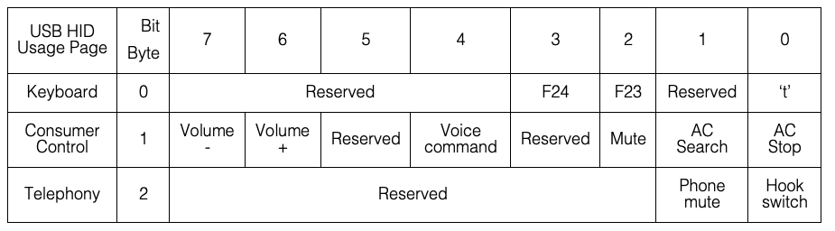
The XVF3610 defines a default Usage Page ID and Usage ID for each bit in the HID Report as seen in the default HID Report table. It also supports changes to the Usage ID for each non-reserved bit at boot-time via the Data Partition. Changes to the Usage Page ID are not supported, and each byte in the HID Report pertains to a specific Usage Page ID as shown in the table below.
HID Report Byte |
Usage Page |
Usage Page ID |
|---|---|---|
0 |
Keyboard |
7 |
1 |
Consumer Control |
12 |
2 |
Telephony |
11 |
To change the meaning of a bit in the HID Report, include the SET_HID_USAGE_HEADER and SET_HID_USAGE commands in the Data Partition. For example, the following commands issued from the Data Partition change the meaning of byte 1 bit 1 from Application Control (AC) Search to Media Select Telephone:
vfctrl_usb SET_HID_USAGE_HEADER 1 1 12
vfctrl_usb SET_HID_USAGE 9 140
The SET_HID_USAGE_HEADER command establishes byte 1, bit 1 as the target location within the HID Report for the subsequent operation. Its first and second arguments make the subsequent SET_HID_USAGE command target byte 1 and bit 1, respectively, in the HID Report. Its third argument specifies the Consumer Control Usage Page as the qualifier for the subsequent SET_HID_USAGE command. The SET_HID_USAGE command changes the meaning of the HID Report byte and bit targeted by the most recent SET_HID_USAGE_HEADER command, byte 1 and bit 1 in this example. Its first argument determines the number of bytes required to store the second argument. The value 9 specifies a one-byte value (less than 256). The number 10 specifies a two-byte value (less than 65536). The XVF3510 does not support length values greater than two bytes. The second argument to the SET_HID_USAGE command specifies the Usage ID to associate with the targeted byte and bit. In this example, the one-byte value 140 (0x8C) changes the meaning of byte 1, bit 1 in the HID Report to Media Select Telephone.
NOTE: Changes to HID usage can occur only at boot-time via the Data Partition. The SET_HID_USAGE command has no effect when received after the boot process completes and USB operation begins.
HID report generation
Configuration of the HID triggers has been extended v4.6
The XVF3610 can send a HID Report when a GPI pin detects an interrupt (logic edge transition event). When interrupts are enabled using SET_GPI_INT_CONFIG, the HID Report generator automatically services the interrupt generating a new report. The HID generation features are listed below:
The HID Report changes upon assertion (positive edge) or de-assertion (negative edge) of a GPI pin
The HID Report supports detection and reporting of multiple events
Control commands allow boot-time configurable mapping between each GPI pin and each HID Report bit
Each GPI pin positive edge asserts a bit in the HID Report; each negative edge enables de-assertion of the bit; sending the HID Report to the USB host de-asserts each bit previously enabled for de-assertion
When no event has occurred, depending on “set idle” configuration by the host, the XVF3610 will either reply with a de-assert report (default) or NAK (set to idle by the host)
NOTE: HID idle behaviour is platform-specific and rarely does the high-level application code have any control over the settings. Linux, for example, typically silences the devices by issuing an indefinite idle (NAK report if no change). Other platforms such as MacOS, on the other hand, leave the device verbose by not issuing an idle (report always sent).
The HID Report generator requires configuration of each GPI pin mapped to a HID Report bit to generate interrupts on both edges.
The default mapping between GPI pins and HID Report bits is:
GPI Pin |
HID Report bit |
|---|---|
0 |
F23 |
1 |
F24 |
2 |
None |
3 |
None |
Use the SET_GPI_INT_CONFIG command to configure a GPI pin that triggers a change in the HID Report. For example, the following command configures GPI pin 0 to generate interrupts on both edges, which enables the HID Report logic:
vfctrl_usb SET_GPI_INT_CONFIG 0 0 3
The first argument is a reserved value and should be set to 0. The second argument makes the command target pin IP_0. The third argument selects both edges for the interrupt.
The Data Partition allows changes to the mapping of GPI pins to HID Report bits at boot-time using the SET_HID_MAP_HEADER and SET_HID_MAP commands. The SET_HID_MAP command has no effect when received after the boot process completes and USB operation begins. For example, the following commands included in the Data Partition change the mapping so that an interrupt on pin IP_1 results in the XVF3610 reporting a Voice Command instead of an F24:
vfctrl_usb SET_HID_MAP_HEADER 0 1
vfctrl_usb SET_HID_MAP 1 4
The SET_HID_MAP_HEADER command establishes the GPI pin for subsequent mapping operations. Its first argument is reserved and should be set to 0. Its second argument makes the subsequent SET_HID_MAP command target pin IP_1. The SET_HID_MAP command changes the association between the GPI pin targeted by the most recent SET_HID_MAP_HEADER command, IP_1 in this example, and the control bits in the HID Report. Its two arguments state the HID Report byte and bit, respectively, to associate with the targeted GPI pin. In this example, byte 1, bit 4 associates the Voice Command control bit with IP_1 as can be seen in the default HID Report table.