General Purpose Outputs
The following commands are available to write and control GPOs:
COMMAND |
TYPE |
ARGS |
DESCRIPTION |
|---|---|---|---|
SET_GPO_PORT |
uint32 |
2 |
Write a value to all pins of a GPIO port.
Arguments are <Port Index> <Value>.
|
SET_GPO_PIN |
uint8 |
3 |
Write to a specific GPIO pin.
Arguments are <Port Index> <Pin Index> <Value>.
|
SET_GPO_PIN_ACTIVE_LEVEL |
uint8 |
3 |
Set the active level for a specific GPO pin.
Arguments are <Port Index> <Pin Index> <0: active low, 1: active high>.
By default, all GPO pins are active high
|
SET_GPO_PWM_DUTY |
uint8 |
3 |
Set the PWM duty for a specific pin. Value given as an integer percentage.
Arguments are <Port Index> <Pin Index> <Duty in percent>.
|
SET_GPO_FLASHING |
uint32 |
3 |
Set the serial flash mask for a specific pin. Each bit in the mask describes the GPO state for a 100ms interval.
Arguments are <Port Index> <Pin Index> <Flash mask>.
|
Note
All GPOs have a weak pull-down (~30kΩ) during reset and initialised to logic low on device boot and will always drive the pin thereafter.
To illustrate usage of the GPOs the following section considers four common examples. Writing to a GPO pin, configuring a PWM output, generating a blink sequence and driving a three colour (RGB) LED.
The following commands toggle OP_2 high then low (XVF3610-UA shown for example):
vfctrl_usb SET_GPO_PIN 0 2 1
vfctrl_usb SET_GPO_PIN 0 2 0
To set all GPOs high and then low:
vfctrl_usb SET_GPO_PORT 0 15
vfctrl_usb SET_GPO_PORT 0 0
The PWM runs at a fixed 500Hz frequency designed to minimise visible flicker when dimming LEDs and supports 100 discrete duty settings to permit gradual off to fully-on control.
The following commands illustrate setting individual PWM frequencies on each output by setting GPO pins 0, 1, 2 and 3 to output 25%, 50%, 75% and 100% duty cycles respectively:
vfctrl_usb SET_GPO_PWM_DUTY 0 0 25
vfctrl_usb SET_GPO_PWM_DUTY 0 1 50
vfctrl_usb SET_GPO_PWM_DUTY 0 2 75
vfctrl_usb SET_GPO_PWM_DUTY 0 3 100
Setting a pin duty to 100% is the same as setting that pin to high.
Each GPO is driven from the LSB of an internal 32bit register, which is rotated by one bit every 100mS.
The figure below shows how the blinking sequence works:
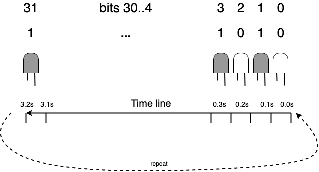
Fig. 19 Use of 32 bit word is used to define the blinking function of GPO
The following commands configure the following:
GPO pin 0 blinking, ON for 1.6 seconds, then OFF for 1.6 seconds, i.e. a period of 3.2 seconds;
GPO pin 1 blinking, ON for 0.8 seconds, then OFF for 0.8 seconds, i.e. a period of 1.6 seconds;
GPO pin 2 blinking, ON for 0.1 seconds, then OFF for 0.1 seconds, i.e. a period of 0.2 seconds;
vfctrl_usb SET_GPO_FLASHING 0 0 4294901760 # equivalent to pattern: xFFFF0000
vfctrl_usb SET_GPO_FLASHING 0 1 4042322160 # equivalent to pattern: xFF00FF00
vfctrl_usb SET_GPO_FLASHING 0 2 2863311530 # equivalent to pattern: xAAAAAAAA
Note that a GPO pin can be set to both a PWM duty cycle, and to flashing by issuing both a GPO_SET_PWM_DUTY instruction and a SET_GPO_FLASHING instruction for the same port and pin.
Where RGB LEDs are connected to three GPO pins (0 = Red, 1 = Green, 2 = Blue) automated colour sequencing can be programmed. For example, to colour cycle between Red-Yellow-Green-Cyan-Blue every 3.2 seconds:
vfctrl_usb SET_GPO_FLASHING 0 0 65535 # 0 x0000FFFF
vfctrl_usb SET_GPO_FLASHING 0 1 16776960 # 0 x00FFFF00
vfctrl_usb SET_GPO_FLASHING 0 2 4294901760 # 0 xFFFF0000