Signal flow and processing
The arrangement of the blocks, with respect to the device Input & Output and the XVF3610 audio processing pipeline, is shown below:
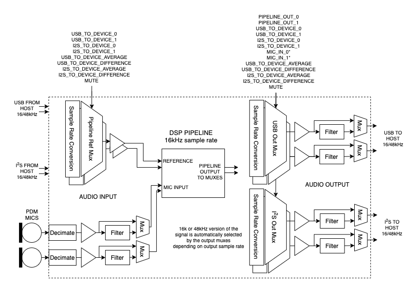
Fig. 9 XVF3610 input, output and audio signal routing
The blocks supported are as follows:
Signal Multiplexers. These allow dynamic selection (switching) of signals. The signals available depend on the multiplexer position.
Gain Blocks. These are blocks that apply a variable bit shift (left or right) and, in the case of left shift, saturate in the case of overflow. Because they are shifters, the gain applied is a power of two.
Filter Blocks. The filter blocks consist of two cascaded biquad units. Each of the five coefficients per stage is directly manipulated via the control utility.
The commands to control the audio multiplexes (Mux) blocks and the source and destination index numbers are listed in the following sections.
The XVF3610 provides a flexible routing control scheme to configure signal routing through the pipeline itself, providing flexibility useful in:
Hardware testing of mics by monitoring the raw mic signal.
Improving pipeline performance by filtering known noise sources at the raw mic input.
Monitoring and debugging of reference signals and mic signals during development.
Compensating for gain offset in reference signal.
Supporting specific audio connectivity requirements such as obtaining the reference signal from I2S.
Inserting audio filtering where a speaker is connected downstream of the XVF3610 via I2S.